Logic Analyzer Adapter for Xilinx boards
Description
The Intronix Logicport
is a small USB-based logic analyzer. It has 34 channels, two of which
can be used as clock inputs, and does state analysis at 200 MHz. Sample
depth without compression is 2048 samples per channel. While the
Logicport is modest in specifications, for many tasks it may well be
all you need. I mainly use the Logicport for Xilinx FPGA projects.
The Logicport connects to the system under test using one of three
ways:
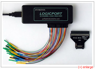
- The Logicport comes standard with a 38-wire flying lead probe. These are 38
individual color-coded wires - 34 signal and 4 ground wires - which you
connect one by one.
- A 38-pin Mictor
("Matched Impedance Connector") adapter is also available.
- The Logicport uses a standard 40-pin IDC connector, so you may be
able to use a 40-wire IDE hard drive cable as test lead if clock
frequencies are low enough and your cable short enough. If you use an
IDE hard drive cable as test lead, make sure the IDE cable is a full
40-wire cable, and not one with pin 20 disabled.
Logicport logic analyzer with flying leads. To the right, the Mictor
adapter.
Problem
Plugging 38 color-coded leads on 38 header pins on my Xilinx
Development Board is time-consuming and error-prone.
Solution
Instead of connecting through a flying lead probe, connect through a
custom adapter.
Benefits:
- The adapter simply plugs into the target system. No flying leads.
- The Logicport plugs into the adapter. No cables.
Xilinx to Logicport adapter
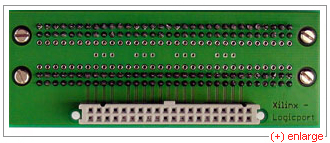
| Adapter, front view. |
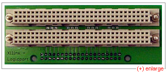
Adapter, back view. |
 |
 |
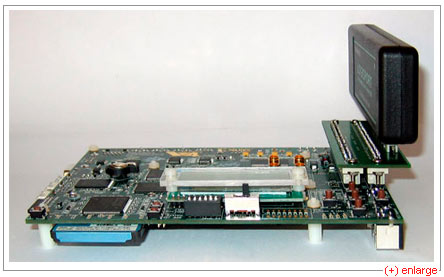
Adapter sitting on a Xilinx ML403, using the
Xilinx Generic Interface (XGI) connector. Other Xilinx developments
boards feature the same connector. Please note the XGI connector is
non-polarized. Make sure you do not plug in the adapter upside-down.
Plugging in the adapter upside-down will short some FPGA outputs to
ground, possibly damaging them.
ML403 board, with logic analyzer sitting on adapter.
This setup allows you to look at 32 signals, a clock enable and a
clock inside the FPGA in real time at reasonable cost.
Ground loops
When connecting the Logicport to a circuit, you are connecting the
circuit ground to the PC ground through the USB cable. If circuit
ground and PC ground have a different potential, connecting them
produces a ground loop. This is a general problem, which may also occur
in USB oscilloscopes, for instance.
A simple solution against ground loops, sufficient for occasional
use, is using a notebook with the AC cord unplugged, running off the
battery. My personal choice has been to put a 100VA isolation
transformer Block
TIM-100 between notebook and mains and forgetting all about ground
loops. Connecting the notebook to the network using unshielded twisted pair ethernet
does not break the isolation.
Availability
I neither manufacture nor sell these adapters. If you want one, you
will have to make one yourself. If you wish to have the printed circuit
board made for you, download the archive for the adapter and extract
all files. Send the .brd file to a PCB house such as pcb-pool.
The .brd file is an Eagle format file. Ask for a
double-sided PCB with solder mask, no silkscreen, no electrical
testing.
Downloads
The schematics and board layout can be downloaded:
You can use the sample ISE project as a simple electrical test. You
should get the following waveform:
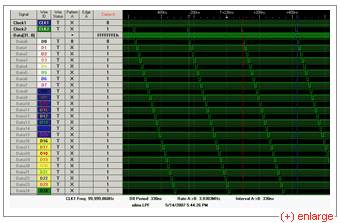
Ring counter output.
Last update page: October 9, 2007
