DVB-S Extension board
Introduction
A PC with a digital TV card such as those made by Technotrend and sold by Hauppage
can be turned into a set-top box using freely available software such
as Linux and vdr.
At the heart of this set-top box one often finds a full-featured DVB-S
card. These cards combine a satellite tv tuner and a hardware MPEG2
decoder. The tuner receives the satellite TV signal and the MPEG2
decoder converts it to a signal a normal TV set can understand, such as
PAL. One only needs to add an infrared remote control receiver such as LIRC
to sit back and enjoy TV.
The board I happen to own is a Technotrend/Hauppage DVB-S 1.3. Using a
small circuit one can improve the quality of the TV image, add a
digital sound output and a remote control receiver. This document
describes such a circuit, should you wish to build one.
The extension board works equally well under Linux as under Windows. I
refer to Linux throughout this page merely because that is what I feel
comfortable with.
Design Goals
The board should be complete but minimal.
- The board should be a complete implementation of all features
provided by the J2 connector:
- Composite and RGB output
- Stereo analogue and digital SPDIF audio output
- Infrared remote control input
- The board should also be a minimal implementation. There is an
endless list of features one might add, all of which are "nice to have"
for a set-top box, but which add to the complexity and cost. I prefer
simplicity.
Also, the board has to be easy to solder. Designs which use
surface-mount devices (SMD) are nice but too difficult for me to solder.
The DVB-S card TV outputs are fragile and easily damaged; the board
should protect them against short-circuits and overvoltage.
And, of course, it should provide great video quality. Enjoying an
excellent TV image is what we're building it for!
Design Choices
After having looked at all available designs, I chose to implement
the circuit as a small daughterboard which can be clipped on the back
of the DVB-S card. This way the distance between J2 input and SCART
output connectors is minimal. There is no need for long flat cables and
their connectors. Picture quality can only benefit from this.
Optical SPDIF output (Toslink) was chosen instead of coax to have
galvanic isolation between the set-top box and any audio equipment you
might want to connect. This avoids
ground loops.
Although it is possible to route everything on a single-sided board, I
prefer a double-sided PCB: allows for better shielding and a nice
ground plane, resulting in less noise.
The DVB-S card interface
Let's see what signals the DVB-S card provides us with.

The connector we're interested in is the one marked "J2". The pins of
this connector are numbered as follows:
J2 pin numbering
| 10 |
9 |
| 8 |
7 |
| 6 |
5 |
| 4 |
3 |
| 2 |
1 |
where pin 1 is the pin in the first row on the the right column. On the
DVB-S card pin 1 is marked with a small triangle. The pinout of the J2
connector depends upon a Linux kernel parameter
vidmode:
J2 pinout versus kernel parameter
| Pin |
CVBS+RGB OUT vidmode=1 (default) |
CVBS+YC OUT vidmode=2 |
YC OUT vidmode=3 |
| 1 |
Composite Video output |
Composite Video output |
Y - Luminance |
| 2 |
+5V |
+5V |
+5V |
| 3 |
Blue Video output
|
- |
- |
| 4 |
SPDIF output |
SPDIF output |
SPDIF output |
| 5 |
Green Video output |
Y - Luminance |
- |
| 6 |
Right Audio output |
Right Audio output |
Right Audio output |
| 7 |
Red Video output |
C - Chroma |
C - Chroma |
| 8 |
Left Audio output |
Left Audio output |
Left Audio output |
| 9 |
Infrared receiver |
Infrared receiver |
Infrared receiver> |
| 10 |
Ground |
Ground |
Ground |
The default is just fine for us. This provides us with PAL
composite (pin 1) and component video (red, green and blue: pins 7, 5,
3), analogue (pins 6, 8) and digital (pin 4) sound and a place to
connect our remote control receiver (pin 9).
The extension board uses the "auxiliary connector" as mechanical
support only.
The TV interface
In Europe most consumer TV sets have
SCART
connectors at the back; they are the most common way of connecting a
video, DVD player or set-top box to a TV. The connector carries stereo
audio and video signals both from video to TV for playback and from TV
to video for recording.
In the picture below, the female connector at the left is the one found
at the back of TV sets, video recorders and DVD players; SCART cables
usually are male-male and use the connector at the right.
If your TV has more than one SCART connector chances are the connectors
differ slightly in the video signals they support. Usually the first
connector is for composite and RGB component video while the second
connector is for composite and S-Video signals. Careful reading of your
TV's manual may be necessary.
Here's the pin numbering of the SCART connector :
SCART connector pinout
| Female SCART at TV/VCR/DVD |
Male SCART at the cable |
|
|
When only interested in playback the
pinout of a SCART connector simplifies to:
Playback-only SCART connector pinout
| Pin |
Playback Composite/RGB |
Playback S-Video |
Signal |
| 1 |
Audio right out |
Audio right out |
|
| 3 |
Audio left (or mono) out |
Audio left (or mono) out |
|
| 4 |
Common Audio ground |
Common Audio ground |
|
| 5 |
Blue ground |
- |
|
| 7 |
Blue output |
- |
|
| 8 |
Source select |
Source select |
High (9.5-12V): Input from SCART, 4:3 aspect
ratio
Mid (5-8V): Input from SCART, 16:9 aspect ratio
Low (0-2V): Input from TV tuner |
| 9 |
Green ground |
- |
|
| 11 |
Green output |
- |
|
| 13 |
Red ground |
Chrominance ground |
|
| 14 |
Blanking ground |
- |
|
| 15 |
Red output |
Chrominance output |
|
| 16 |
Insert control |
- |
High (1-3V): RGB
Low (0-0.4V): Composite |
| 17 |
Composite video ground |
Luminance ground |
|
| 18 |
RGB Switching control ground |
- |
|
| 19 |
Composite video output |
Luminance output |
|
| 21 |
Common shield ground |
Common shield ground |
|
Note composite video and luminance (black-and-white information) share
the same pin. If you get a black and white image the most probable
cause is that the DVB-S card is sending S-Video, but the TV thinks it
is composite video, or the other way round.
A more complete description of these signals can be found at Eric-Paul
Rebel's site.
Composite, RGB, S-Video: What to choose?
When in doubt which video signal to use, avoid composite video if
you can as signal quality is lowest. When having to choose between RGB
and S-Video, I prefer RGB: colors seem more vibrant.
The SPDIF interface
Additionally, you can connect the DVB-S card to your home theatre
sound system using the SPDIF (Sony Philips Digital InterFace)
connector, just like you would connect a DVD player. This allows
listening to TV sound from your home theatre speakers. Two kinds of
SPDIF cable exist; one is a copper coaxial cable with RCA connectors;
the other is Toslink optical fibre. The extension board has an optical
sound out connector for Toslink optical fibre.
Digital mono or stereo sound should work out of the box.
If you wish to listen to Dolby Digital (also called AC3) or DTS sound
using vdr take a look at the AC3-over-DVB patch.
The AC3-over-DVB patch encapsulates the AC3 or DTS data into special
headers and sends them via the SPDIF connector of the card. Note the
AC3-over-DVB patch does not decode AC3 nor DTS; it merely sends it.
Most, but not all, home theatre systems then correctly interpret the
encapsulated stream. Here is a list
of home theatre systems that are reported to work OK.
The circuit
There are a number of circuits which do the job, but the circuit made
by
Thomas
Breuer seems to be the reference, and is the one this work is based
on. His design provides a nice balance between preserving excellent
video quality while protecting the delicate video outputs of the DVB-S
board.
While reading the
schematic,
note:
- the +5V power supply for the analogue components is distinct from
the +5V power supply for digital components. The 7805 avoids noise from
the PC power supply getting to the infrared receiver or to the video
circuit.
- the J2 video outputs are best modeled as current sources.
- the TV video inputs are best modeled as 75R resistances.
- in normal operation, the BAT42 Schottky diodes do not conduct;
they are there to protect against over- or undervoltage.
- in normal operation, the 10R and 51R resistors have no influence,
being in series with a current source. They are there in case of over-
or undervoltage.
- All four J2 video outputs - composite, red, green and blue - are
1V peak-to-peak into 75R. The composite signal carries 0.3V
synchronisation and 0.7V video, whereas red, green and blue are 1.0V
video only, no sync. Some TV's expect all RGB signals to be 0.7V and
produce images which are too bright when fed 1.0V. Given that the J2
video outputs are current sources, the 180R resistor in parallel with
the 75R of the TV video input reduces red, green and blue voltage to
0.7V peak-to-peak. The 22R resistor in series brings total impedance
(22R + 180R||75R) back to 75R so filter characteristics don't change.
- The circuit slightly emphasises
higher frequencies; this corresponds to slightly accentuating
picture detail.
- J2 pin 1 provides the composite output. It is a current source
which is loaded by two circuits:
- the filter on the DVB-S PCI card between J2 pin 1 and the
RCA/cinch video output on the backplate of the PCI card.
- the filter on the extension board between J2 pin 1 and the
composite output on the SCART connector.
The frequency response of the composite output suffers from being
loaded by both circuits. However, this is not a problem if you are
using the SCART output in RGB mode. In RGB mode the composite output is
only used for sync, and sync gets through fine. It is also not a
problem if you are using the extension board for S-video output with
vidmode=2, as this does not use J2 pin 1 at all. (From information
provided by Th. Breuer)
The board
The board was designed using the Eagle software package. You
can download and use Eagle for free for small projects like this.
Note the SPDIF digital audio output is routed away from and
perpendicular to the video signals. This is to avoid interference
between the digital sound and the analogue video signals.
Also, if you choose to make the board yourself you probably don't have
plated-through vias. This means you will have to solder some components
on both solder and component side and insert wires in those vias which
don't have components in them.
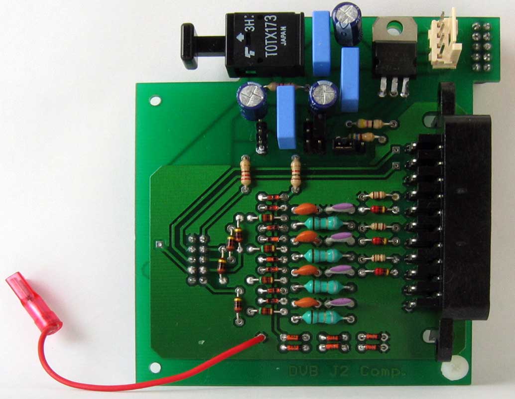
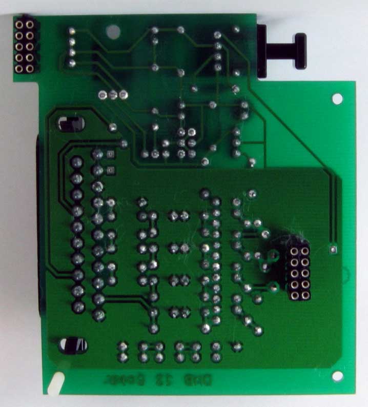
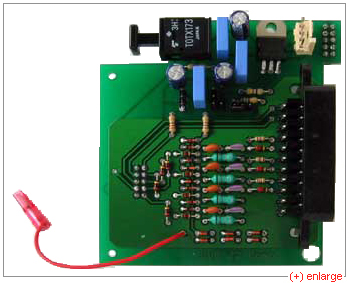
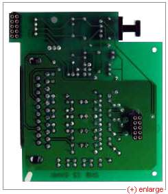
Finished board
| Finished Board, Component side |
Finished Board, Solder side |
|
|
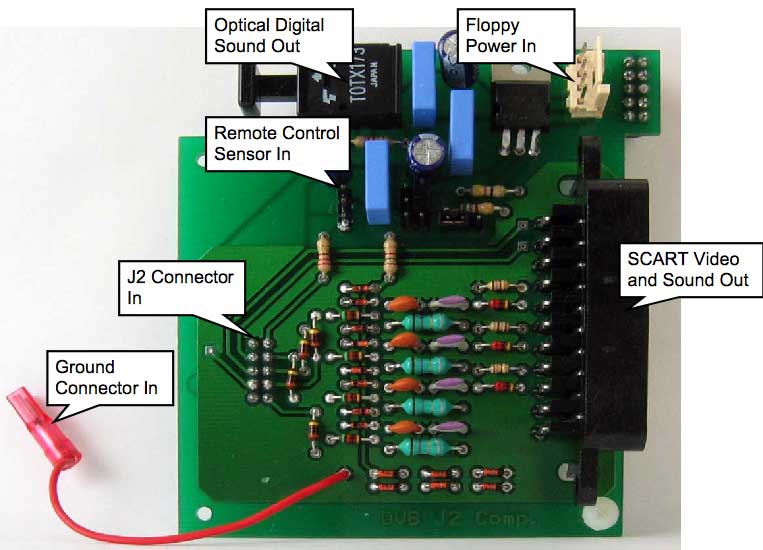
This is what the various connectors are used for:
Test before you plug in
Before trying the board it's a good idea to do a few test measurements.
Verify there are no short circuits between any of the four
(Composite+RGB) video inputs and ground, or between any of the four
video inputs.
Next, let's try connecting the floppy power connector. You should
measure
- 12V at the input of the 7805.
- 5V at the output of the 7805.
- 1.9V at the leg of R13 which is connected to the diodes.
Don't forget to check you haven't shorted any of the auxiliary
connector pins when soldering.
Well grounded
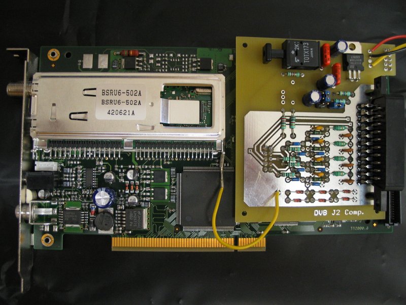
And this is how it looks when clipped on the back of the DVB-S card:
The red wire running from the "test point" of the extension board to
the sheet metal of the tuner ensures a good ground. The four video
signals (Composite+RGB) from four J2 pins each drive a 75 ohm load. The
return current, however, has got to go through a single J2 pin, so the
impedance of this one ground pin might become an issue. Connecting the
ground of the extension board with the metal of the tuner solves the
problem. The connector which clips on the tuners' legs is called a "2.8
mm female Faston" connector, BTW.
Isolated
Maybe you can just see the plastic foil which I have put between the
daughterboard and the DVB-S card. The two don't touch, but adding a
little bit of extra isolation just to be on the safe side doesn't hurt.
Jumpers
There are two jumpers on the board:
Source Select Jumper
| Source Select Jumper (JP4) |
|

|
TV switches automatically to SCART
connector when PC turned on.
Screen format 4:3. (default) |

|
TV does not switch automatically to SCART
connector
when PC turned on. Switch to SCART
connector using the remote control. |
 |
TV switches automatically to SCART
connector when PC turned on.
Screen format 16:9. |
Insert Jumper
Insert Jumper (JP2)
|
|
 |
Use RGB component video signal. (default) |

|
Use composite video signal. |
Try looking at a test card once using composite video, and once
using RGB. You'll see the difference.
Infrared remote control
The infrared unit of the DVB-S card only understands RC-5 and RC-MM
codes. TV sets, DVD players and video recorders made by Philips usually
use these codes, so if you have a universal remote control you might
want to try to set the remote to Philips equipment. When choosing a
sensor, remember the RC-5 specification states the carrier frequency to
be 36 kHz. A TSOP
1736 or 1836 works fine.
I am using a TSOP 1736 mounted in the front panel of the PC, with a
small 10µF electrolytic capacitor soldered in parallel with its
power leads.
Note: the infrared receiver will only work if you do not have a Common
Interface/Conditional Access Module installed.
On the software side, using the DVB-S cards' infrared receiver means
you don't need lirc_serial kernel drivers nor a lirc
daemon to run vdr. The vdr-remote
plugin is all you need. Of course, if you prefer, you can keep
using lirc.
I have experimented a bit using both a serial LIRC receiver and the
DVB-S card infrared receiver, and both work fine. There are situations,
however, where the DVB-S infrared is preferable. For a vdr set-top box,
it is preferable to use the slowest CPU which does the job. A slower
CPU generates less heat and needs less cooling. Less cooling means fans
run slower and generate less noise. Noise only distracts from the movie
you're watching. However, the speed requirements of vdr may vary
wildly. Just watching TV needs very little - say, 256 MHz - while scanning a
recording for commercials runs smoother on a fast 2 GHz CPU. I am
experimenting with Pentium IV clock modulation, using programs such as speedfreqd to
dynamically change CPU frequency as needed. The lirc_serial kernel module,
however, seems to have difficulties with CPU clock frequency dropping
from 2GHz to 256MHz; it becomes unresponsive to the remote control.
This seems to be a driver problem (as of kernel 2.6.0). The DVB-S
cards' infrared receiver does not have this problem.
Installing the card
Of course, when the card is installed the SCART connector is inside the
PC. Let me repeat this: the SCART connector will be inside the PC. This
means you need to find a way to get the cable out. I chose to make a
small hole in the shield around the motherboard connectors. There's
also a strain relief around the SCART cable, so someone yanking the
cable doesn't yank the innards of the PC out. An alternative would be
installing a female SCART connector on the back panel, connecting it to
the extension board with a short cable.
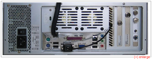
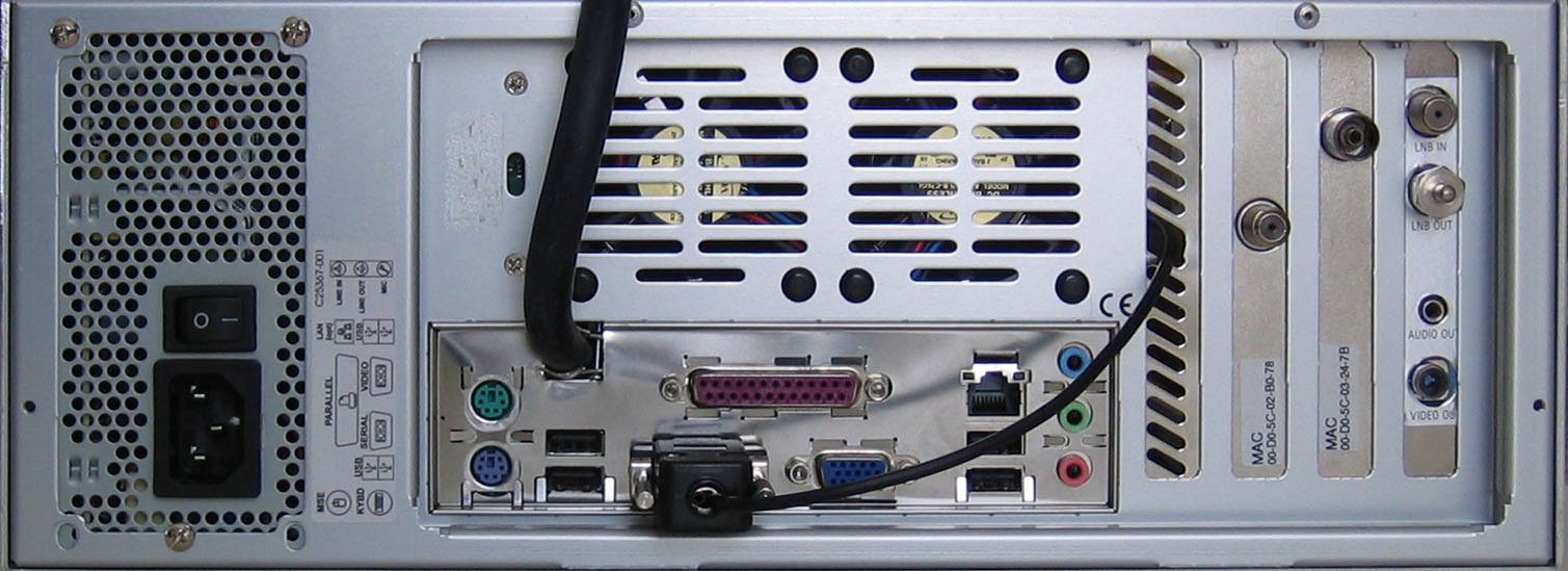
This PC has, from left to right, one
budget DVB-S, one budget DVB-T and one full-featured DVB-S 1.3 card. On
this picture you can see the big, black SCART cable and the much
smaller lirc_serial cable.
If you connect one TV using the SCART
connector please don't try to connect a second TV using the RCA video
out connector at the back of the PCI card: SCART and RCA are not
intended to be connected simultaneously. The DVB-S card may not be able
to handle the load of two TV's in parallel. Connecting the audio output
at the back of the PCI card to your stereo equipment while you're using
the SCART connector is not a problem.
Picture gallery
- Karim (kafifi at easyconnect dot fr) sent this picture of his
extension board clipped on to a DVB-S 1.5:
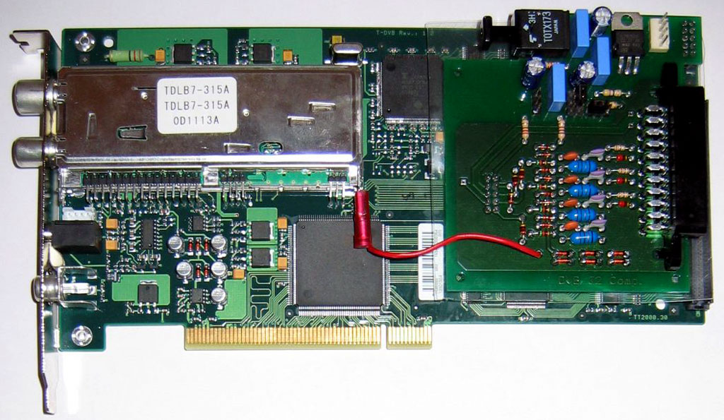
- The board also fits the (rare) full-featured DVB-T 1.2 cards:
Downloads
The latest Eagle schematics, board layout
and Gerber/Excellon files
can be found here: Eagle design files
(500 kb download). The dvbj2.brd file in this archive can be
sent to PCB manufacturing services such as www.pcb-pool.com.
Cost
The main cost is the printed circuit board; the components only cost
about 16€. The cost of the printed circuit board depends upon whether
you make it yourself or have it made for you, and how many.
Acknowledgements
This design builds upon information from
vdrportal,
vdr-wiki
and board designs from
Thomas
Breuer,
Frank
Hermann,
fdm-ware and many others.
Thanks to all those who provided feedback.
Last update page: February 21, 2005